CHAPTER 1 A Crash Course in Java (Incomplete)
a class definition contains:
- constructors
- methods
- fields
Object-oriented programming follows the “client-server” model. The client code requests a service by invoking a method on an object.
In Java, an object value is always a reference to an object, or, i n other words, a value that describes the location of the object.
- do a deep copy by implementing/using clone method
The special reference nul l refers to no object. You can set an object variable to null: - worldGreeter = null;
- If you invoke a method on a null reference,a NullPointerException is thrown.
However, in Java, a method can never update the contents ofa variable that is passed as a parameter.
CHAPTER 2 The Object-Oriented Design Process
From Problem to Code
The analysis phase
- The goal of the analysis phase is a complete description of what the software product should do. (called functional specification)
- user manual
- a set of user cases
- focus on what it should be done
The Design Phase
- Each class must be specified precisely, listing both its responsi bilities and its relationship to other classes in the system.
- major goals:
- Identify the classes
- Identify the responsibilities of these classes
- Identify the relationships among these classes
- the end result consist of the following artifacts:
- A textual description of the classes and their most important responsibilities
- Diagrams of the relationships among the classes
- Diagrams of important usage scenarios
- State diagrams ofobjects whose behavior is highly state-dependent
Implementation phase
Implement the prototype and refine your design as needed
The object and class Concept
- Objects are entities in a computer program that have three character istic properties:
- State (like the property variables in there)
- Behavior (like methods)
- Identity
Identifying classes
- A simple rule of thumb for identifYing classes is to look for nouns in the functional specification, such as “Mailbox”, “Menu” etc.
Identifying Responsibilities
- Just as classes correspond to nouns in the problem description, respon sibilities correspond to verbs
Relationships Between Classes
- Three relationships are common among classes:
- Dependency (“uses”)
- Aggregation (“has”)
- Inheritance (“is”)
Dependency (“uses”)
One important design goal is to minimize the number of dependency relationships; that is, to minimize the coupling between classes. (If one class is unaware of the existence of another, it is also unconcerned about any changes in that other class. A low degree of coupling tends to make it much easier to implement changes in the future.)
Aggregation (“has”)
- Aggregation takes place if objects of one class contain objects of another class over a period of time.
- Aggregation is a special case of dependency. Of course, if a class contains objects of another class, then it is acutely aware of the existence of that class.
- Aggregation is often informally described as the “has-a” relationship. A message queue has a message.
Inheritance (“is”)
- A class inherits from another if all objects of its class are special cases of objects of the other class, capable of exhibiting the same behavior but possibly with additional responsibilities and a richer state.
User case
- Use cases are an analysis technique to describe in a formal way how a computer system should work. Each use case focuses on a specific scenario, and describes the steps that are necessary to bring it to successful completion.
- A use case lists a sequence of actions that yields a result that is of value to an actor.
- A use case should include variations that describe these situations.
CRC card (skipped for now)
- The CRC card method is an effective design technique for discovering classes, responsibilities, and relationships. A CRC card is simply an index card that describes one class and lists its responsibilities and collaborators (dependent classes).
- You make one card for each discovered class. Write the class name at the top ofthe card. Below, on the left-hand side, you describe the responsibilities. On the right-hand side, you list other classes that need to collaborate with this class so that it can fulfill its responsibilities.
- The responsibilities should be at a high level. Don’t write individual methods.
UML Class Diagrams
- The basic UML notation for class diagrams is fairly simple.
- Classes are drawn as boxes
- contains class name, attributes and methods
- You usually do not list all attributes and methods, only the most important ones.
- Often, the types of attributes, parameters, and return values are omitted to conserve space.
- contains class name, attributes and methods
- Classes are drawn as boxes
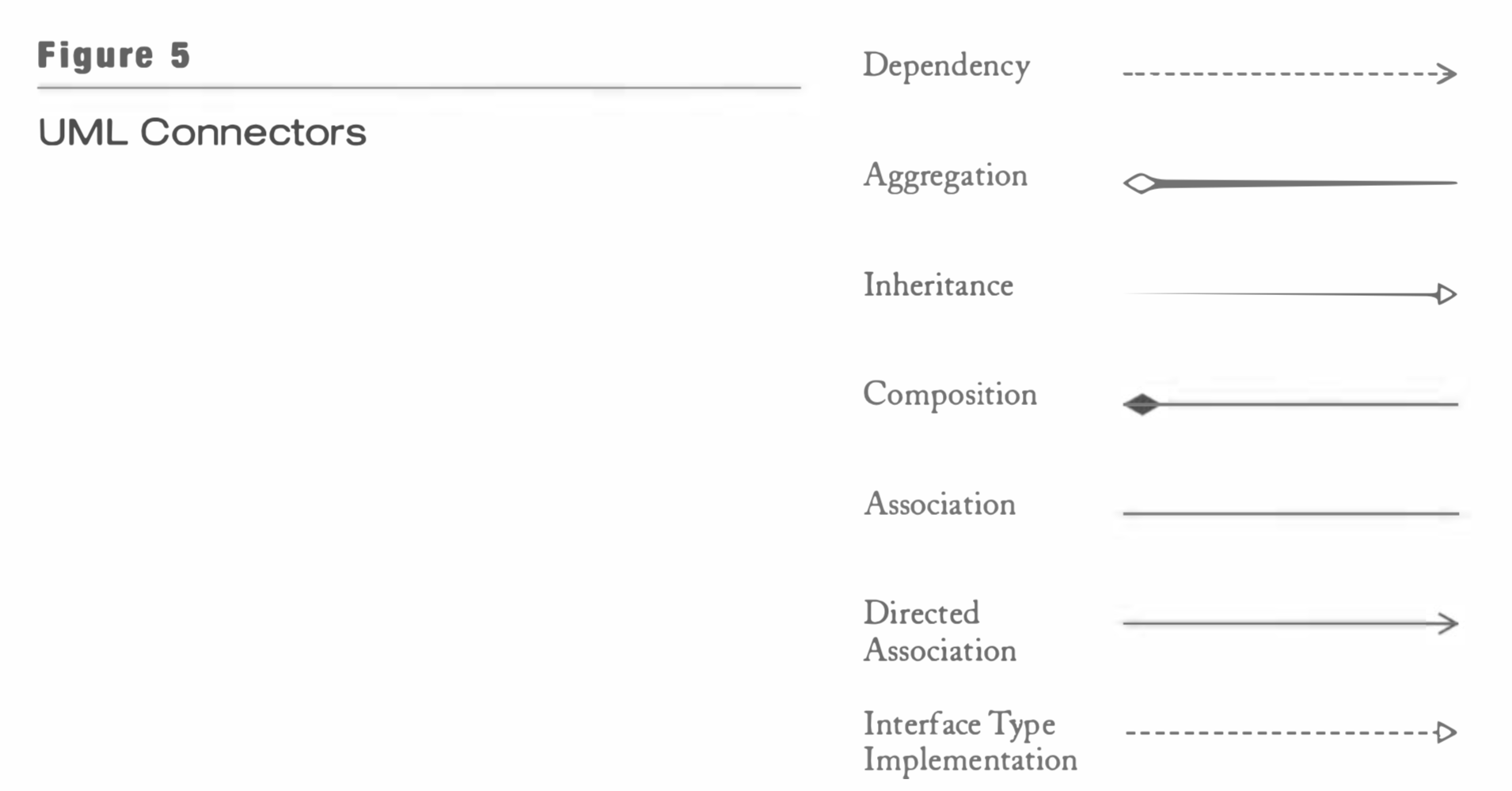
- UML connectors
Sequence Diagram
In contrast, a sequence diagram shows the dynamics of a particular scenario.
- In UML, you use underline to distinguish object rectangles from class rectangles. The text inside an object rectangle has one of the following three formats:
- obj ectName : (1 assName (full description)
- obj ectName (class not specified)
- : (1 assName (object not specified)
- The dashed vertical line that emanates from the object is called the lifeline.
- The rectangles along the lifeline are called activation bars.
State Diagrams
Some objects have a discrete set of states that affect their behavior.
REFERENCE: Object-oriented design & patterns / Cay Horstmann. (Cay S. Horstmann 1959- Hoboken, NJ : Wiley 2006)